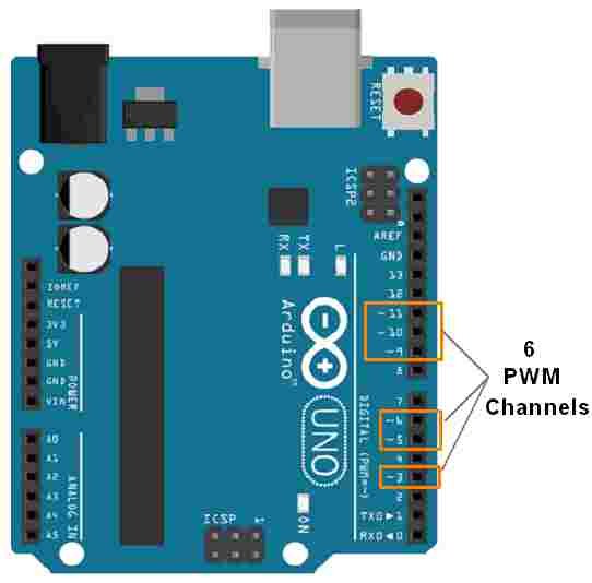

The ATmega168P/328P chip has three PWM timers, controlling 6 PWM outputs. Finally, it's difficult to determine the appropriate constants for a particular duty cycle and frequency unless you either carefully count cycles, or tweak the values while watching an oscilloscope.Ī more elaborate example of manually PWMing all pins may be found here. A second disadvantage is you can't leave the output running while the processor does something else. One major disadvantage is that any interrupts will affect the timing, which can cause considerable jitter unless you disable interrupts.
#ARDUINO PWM FULL#
In addition, you have full control the duty cycle and frequency. This technique has the advantage that it can use any digital output pin. You can "manually" implement PWM on any pin by repeatedly turning the pin on and off for the desired times. Probably 99% of the readers can stop here, and just use analogWrite, but there are other options that provide more flexibility. (Note that despite the function name, the output is a digital signal, often referred to as a square wave.) The analogWrite ( ) function provides a simple interface to the hardware PWM, but doesn't provide any control over frequency. The Arduino's programming language makes PWM easy to use simply call analogWrite ( pin, dut圜ycle ), where dut圜ycle is a value from 0 to 255, and pin is one of the PWM pins (3, 5, 6, 9, 10, or 11). Simple Pulse Width Modulation with analogWrite Generating a modulated signal, for example to drive an infrared LED for a remote control.Providing variable speed control for motors.It will provide an analog voltage between 0% and 100%. Providing an analog output if the digital output is filtered,.If you repeat this on-off pattern fast enough with an LED for example, the result is as if the signal is a steady voltage between 0 and Vcc controlling the brightness of the LED. To get varying analog values, you change, or modulate, that pulse width. The duration of "on time" is called the pulse width. This on-off pattern can simulate voltages in between the full Vcc of the board (e.g., 5 V on UNO, 3.3 V on a MKR board) and off (0 Volts) by changing the portion of the time the signal spends on versus the time that the signal spends off. Digital control is used to create a square wave, a signal switched between on and off. Pulse Width Modulation, or PWM, is a technique for getting analog results with digital means. Arduino Board with an ATmega168 or ATmega328 chip.About Pulse Width Modulation techniques.This tutorial focuses on the Arduino Diecimila and Duemilanove models, which use the ATmega168 or ATmega328.
#ARDUINO PWM HOW TO#
This tutorial explains simple PWM techniques, as well as how to use the PWM registers directly for more control over the duty cycle and frequency. Pulse-width modulation (PWM) can be implemented on the Arduino in several ways.


 0 kommentar(er)
